What limits wind turbine efficiency?
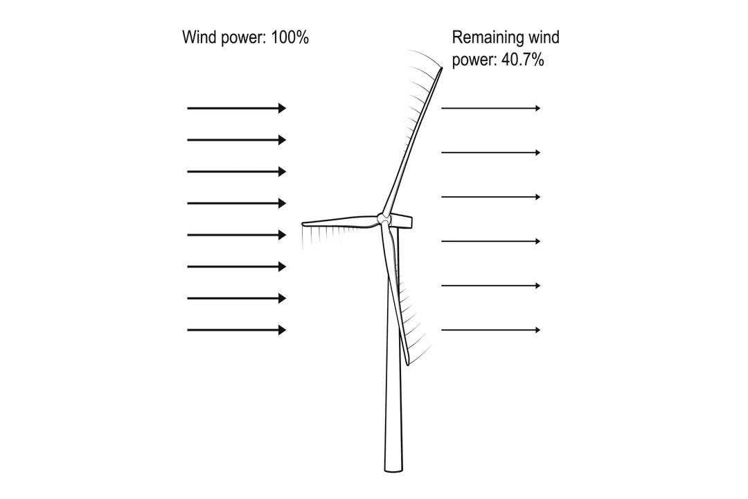
The actual power harvested by a wind turbine is significantly less than the raw kinetic energy passing through its swept area, a reality governed by fundamental physics and engineering trade-offs. Understanding these limitations is key to appreciating the true capability and constraints of wind energy technology. The theoretical upper bound for any wind turbine's performance is a fixed point dictated by fluid dynamics, known as the Betz Limit. This limit, which dictates that no device can capture more than approximately 59.3% (or ) of the kinetic energy in the wind, stems from the necessity of allowing air to move through the rotor area. If a turbine were to capture 100% of the energy, the air would have to stop completely behind the rotor, causing a massive buildup of pressure and halting the flow, effectively preventing any further energy transfer.
# Theoretical Maximum
The concept behind the Betz Limit is rooted in basic conservation laws applied to an ideal, two-dimensional rotor operating in an infinitely large, uniform wind field. The power available in the wind is directly proportional to the cube of the wind speed (). Because of this cubic relationship, the wind speed at the turbine location is perhaps the most dominant external factor determining the potential energy yield, even more so than the rotor's own efficiency rating. The theoretical maximum power coefficient () is fixed at $0.593$.
This theoretical benchmark establishes the dividing line between what is physically possible and what is technically achievable in the real world. While engineers strive to design turbines that operate as close to this $59.3%$ ceiling as possible, reaching it is impossible due to the inherent inefficiencies introduced by mechanical components and imperfect aerodynamics. The power coefficient, , is the metric used to describe how much of the available wind power a turbine actually converts into mechanical power. A turbine operating at its peak efficiency might achieve a in the range of $0.45$ to $0.50$, meaning it captures $45%$ to $50%$ of the available energy, which is still quite close to the theoretical limit.
# Power Coefficient

The power coefficient () is fundamentally the ratio between the actual power extracted by the blades and the total kinetic energy flux passing through the rotor's swept area. This coefficient is not a fixed number for a given turbine; rather, it varies depending on the rotational speed of the blades relative to the wind speed, a relationship quantified by the Tip Speed Ratio (TSR). The TSR is the ratio of the speed of the blade tip to the speed of the incoming wind.
For any given turbine design, there exists an optimal TSR where the reaches its maximum value. Modern, utility-scale turbines are carefully designed to operate near this peak under their rated wind speeds. If the wind speed drops too low, the turbine might not be able to rotate fast enough to maintain the optimal TSR, causing the to fall. Conversely, if the wind speed becomes too high—approaching the turbine's cut-out speed—the blades are often pitched to intentionally reduce the , preventing mechanical overload, even though the available power in the wind is massive.
A practical analysis of turbine operation reveals a constant balancing act involving the TSR. For a fixed-pitch turbine, there is only one TSR that yields the maximum . Modern variable-speed turbines, however, adjust the rotor speed to track the wind speed, allowing them to maintain the optimal TSR across a wider range of wind conditions, thereby maximizing the much more consistently.
# Aerodynamic Factors
Beyond the absolute Betz barrier, aerodynamic factors introduce immediate losses before the energy even reaches the drivetrain. Blade design is paramount here. To maximize aerodynamic performance, the blades must be shaped like airfoils, similar to airplane wings, designed to create lift. However, the geometry of the blade, including its chord (width) and twist, must change from the root near the hub to the tip to ensure that the angle of attack—the angle between the airfoil and the relative wind—is optimal along the entire length of the blade. If the blade is not perfectly designed and twisted for the expected wind profile, significant portions of the blade will operate inefficiently, generating drag instead of driving rotation.
Turbulence in the incoming air stream also degrades performance. When wind flows over terrain features or encounters the wake created by an upstream turbine, the smooth, laminar flow needed for high lift is disrupted. This chaotic flow reduces the effective lift generated by the blades, resulting in a lower than the theoretical maximum predicted under ideal, uniform wind conditions.
Here is an original consideration regarding flow: While the Betz Limit accounts for an idealized, infinite wind stream, real wind flow is highly three-dimensional and involves complex boundary layer physics on the blades. A subtle but persistent issue for designers is boundary layer separation near the blade tips or at high angles of attack. When the air detaches from the surface—like smoke peeling off a blunt object—it creates significant drag and stalls the blade section, causing an immediate and sharp drop in far greater than minor geometric imperfections. Turbine control systems work constantly to manage pitch angles to forestall this separation, especially during gusts.
# Mechanical Inefficiencies

Once the wind has successfully imparted kinetic energy to the rotor and turned the main shaft, the energy must travel through a series of mechanical and electrical components, each introducing losses. These losses are unavoidable in any real-world machine.
# Drivetrain Losses
The gearbox, which is common in many large turbines, is a major source of mechanical inefficiency. It steps up the slow rotational speed of the rotor (perhaps $10$ to $20$ revolutions per minute) to the high speed required by the electrical generator (often over $1,000$ rpm). Friction in the gear teeth, bearings, and the oil necessary for lubrication converts some of the mechanical energy into waste heat. While modern, well-maintained gearboxes can achieve efficiencies upwards of $97%$ or $98%$, this loss is cumulative across the entire drive train.
Some newer designs, known as direct-drive turbines, eliminate the gearbox entirely by using a large, slower-spinning generator that connects directly to the rotor hub. While this removes gearbox losses, it substitutes them with increased electrical losses in the large, slower-speed generator, which often requires more rare-earth magnets and has a higher mass and material cost. The overall efficiency gain must be weighed against the increased complexity and cost of the generator system.
# Electrical Conversion
The electricity generated, whether via a geared or direct-drive system, is often AC electricity at a variable frequency and voltage because the rotor speed constantly changes. This power must then be conditioned, inverted, or converted by power electronics to match the stable frequency required by the electrical grid. Every step in this electronic conversion process introduces losses, typically manifesting as heat dissipated from the inverters and transformers. While modern power electronics are highly efficient, often achieving $95%$ conversion efficiency, a $5%$ loss here, combined with a $2%$ loss in the gearbox, means that a turbine operating at $50%$ aerodynamic efficiency has already lost nearly $8%$ of its captured energy before it ever leaves the nacelle.

# Site Specific Constraints
Turbine efficiency is not just about the machine itself; it is fundamentally tied to where the machine is placed.
# Wind Speed Distribution
Wind turbines are designed for a specific rated wind speed, typically around $12$ to $15$ meters per second (). Below the cut-in speed (usually $3$ to ), the blades do not rotate, and no power is produced. Above the rated speed, the turbine operates at its maximum power output capacity, often by pitching the blades to shed excess wind, effectively limiting the to keep the output constant.
The efficiency of a wind farm over a year is heavily dependent on the site's Weibull distribution—the statistical pattern of how often different wind speeds occur. A site with very high average wind speeds might result in the turbine spending a lot of time in power-limiting conditions (pitched blades), while a site with lower, but more consistent, winds might allow for longer periods near the peak .
# Wake Effects
In a wind farm, the turbines are placed in rows downwind of each other. The first row extracts energy, creating a wake—an area of slower, more turbulent air—that impacts the turbines behind it. Turbines situated deep within a farm can see their available energy reduced by $10%$ to $20%$ or more due to the wake effect from upstream machines.
This effect means that the overall energy produced by the wind farm, when measured against the total undisturbed wind energy passing through the entire farm's area, is always lower than the sum of the efficiencies of the individual turbines operating in isolation. Designing the spacing and layout to mitigate these wake interactions is critical for maximizing the farm's total energy capture, balancing the need for high turbine density against aerodynamic interference.
This leads to an insight regarding operational siting: If one were designing a micro-grid relying on a small cluster of three turbines, the common error is spacing them along the prevailing wind direction. A more efficient configuration, especially in areas with variable wind direction, might be a triangular or staggered array. This prevents the main turbine wake from consistently shielding the same downwind turbine, promoting better array efficiency even if it slightly increases cable lengths.
# Material and Design Limits
The physical materials used impose constraints on how aggressively a turbine can be pushed toward the Betz Limit. The blades must be strong enough to withstand extreme wind loading—sometimes exceeding hurricane force—without breaking, while also being light enough to start rotating in light breezes.
The structural integrity dictates the maximum size and stiffness. Very long, slender blades are necessary to capture more energy (since power is proportional to the swept area, ), but they become more susceptible to excessive deflection and flutter. This forces engineers to design turbines that prioritize safety and longevity over squeezing out every last tenth of a percent of the theoretical .
The need for an optimal TSR introduces another engineering constraint that pulls the design away from the absolute theoretical optimum. For peak aerodynamic performance, the blade tip speed needs to be very high relative to the wind speed (high TSR). However, very high tip speeds lead to increased noise pollution—a major constraint, especially for onshore installations—and greater material stress on the blade tips. Therefore, for many turbines, the operational speed is deliberately kept below the TSR that would yield the absolute maximum to reduce acoustic emissions and mechanical wear, accepting a slight penalty in efficiency for better public acceptance and longer component life.
This design compromise is a necessary trade-off. Consider a hypothetical turbine where the ideal TSR for is $8.5$. However, operating at TSR $7.0$ might reduce by only $2%$, but simultaneously decrease tip noise by $6$ decibels, making the site viable where it otherwise would not be. The resulting energy loss from that $2%$ reduction in over the turbine's lifetime is often accepted because the alternative is no turbine at all at that location.

# Measuring Real Performance
The overall efficiency of a wind turbine system—often termed the Capacity Factor—is a measure that encompasses all the limitations discussed: the Betz limit, aerodynamic flaws, mechanical losses, and site-specific wind availability. While a high-end turbine might have a of $0.50$, its Capacity Factor is much lower, reflecting the fact that the wind is rarely blowing at the precise speed required to maximize that .
Capacity factor is calculated by dividing the actual energy produced over a period (e.g., a year) by the maximum possible energy the turbine could have produced if it ran at its full rated power continuously for that entire period. A modern, well-sited onshore wind turbine might achieve a capacity factor between $30%$ and $45%$. Offshore turbines, benefiting from stronger and more consistent winds, often achieve capacity factors between $45%$ and $60%$. This disparity clearly shows that the primary limit on annual energy capture is often the quality and consistency of the wind resource at the location, not just the technical efficiency of the hardware itself.
In summary, the factors limiting efficiency are layered:
- Physics (Betz Limit): The fundamental $59.3%$ ceiling.
- Aerodynamics: Imperfect blade shape, twist, and local turbulence reduce below the limit.
- Mechanical/Electrical: Friction, gearbox losses, and inverter inefficiencies siphon energy before grid export.
- Operational: Design choices prioritizing noise reduction and structural integrity limit operation at the absolute peak .
- Site Resource: Wind speed variability and wake effects drastically lower the annual capacity factor.
To assess the performance difference between wind and solar, it is useful to compare their respective capacity factors against their theoretical limits. Solar photovoltaic panels have a theoretical maximum efficiency near $33%$, but real-world panels are usually in the $18%$ to $22%$ range, yielding capacity factors often in the $15%$ to $25%$ range in many locations. Wind turbines, even with the Betz Limit restricting them to a lower theoretical capture percentage ($59.3%$), frequently surpass solar's actual capacity factor due to the superior consistency of wind resources in good locations. This comparison underscores that the limitations are relative to the resource itself.
# Control Systems
The control systems installed on modern turbines are specifically designed to push the as high as possible, as close to the optimum TSR as the current wind speed allows, while simultaneously managing the physical limits of the machine. Sophisticated algorithms constantly monitor wind speed and direction, adjusting blade pitch and rotor speed to maintain that optimal performance point.
For example, when the wind exceeds the rated speed, the control system actively reduces efficiency by pitching the blades out of the optimum aerodynamic angle. If it did not do this, the generator would overload and possibly fail, or the blades themselves could be damaged by excessive aerodynamic force. This intentional sacrifice of instantaneous is a critical part of ensuring the turbine's long-term reliability and adherence to safety standards. The control system effectively sets a dynamic, operational limit on efficiency based on safety and grid requirements, which is often lower than the theoretical aerodynamic maximum for a given wind speed.
# Summary of Performance Drop
The actual energy captured is a product of several sequential efficiencies. If one starts with $100$ units of wind power:
| Stage | Typical Efficiency Range | Power Remaining |
|---|---|---|
| Wind Capture () | $45% - 50%$ | $45 - 50$ units |
| Gearbox/Drivetrain | $97% - 99%$ | units |
| Electrical Conversion | $94% - 96%$ | units |
| Site/Array Losses (Annualized) | Varies significantly | units (Capacity Factor) |
While the physical limit restricts capture to $59.3$ units, the real-world turbine delivers only around $40$ units to the grid under ideal conditions (i.e., high capacity factor operation). The ultimate limitation, when assessing power production over a year, remains the resource availability itself, often resulting in capacity factors significantly lower than the peak .
#Videos
The Betz Limit: Why All Wind Turbines are Less Than 59.24% Efficient
Related Questions
#Citations
Betz Limit and the Power Coefficient of Wind Turbines
Wind Energy Factsheet | Center for Sustainable Systems
Turbine Efficiency > Experiment 12 from Renewable ... - Vernier
[PDF] Maximum Efficiency of a Wind Turbine - Digital Commons @ USF
[PDF] Renewable Energy Fact Sheet: Wind Turbines - EPA
How Efficient Are Wind Turbines in 2025? Explained
Wind Turbine Efficiency → Term - Energy → Sustainability Directory
The Betz Limit: Why All Wind Turbines are Less Than 59.24% Efficient
What Is the Power Coefficient (Cp) of a Wind Turbine, and Why Does ...