What causes signal attenuation in circuits?
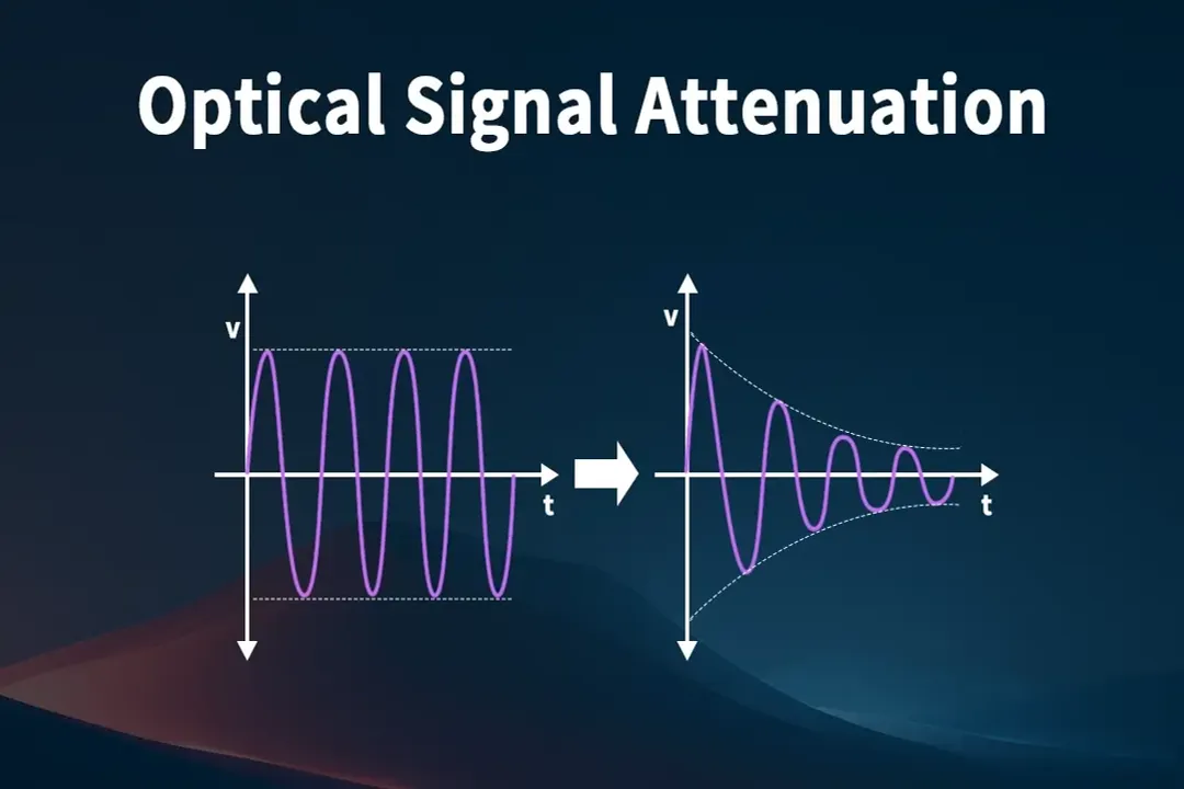
Signal attenuation describes the natural reduction in signal magnitude or power as it travels through a medium, whether that medium is a copper trace on a circuit board, a coaxial cable, or a segment of optical fiber. When dealing with electrical signals, this loss is often quantified in decibels (), which represents the ratio of the output power to the input power. A higher attenuation value means the signal degrades more rapidly, potentially falling below the receiver's sensitivity threshold or introducing unacceptable levels of distortion, particularly in high-speed digital systems. Understanding the root causes is essential for designing any reliable communication or measurement system.
# Core Concept
Fundamentally, attenuation results from energy being removed from the propagating signal wave and converted into another form, most commonly heat, within the transmission medium. This energy dissipation is a universal phenomenon in signal transmission, though the specific mechanisms driving it differ drastically between electrical conductors and optical waveguides. For general electrical engineering purposes, attenuation can be categorized into losses within the conductor itself and losses within the insulating material surrounding it.
# Conductor Losses
In metallic conductors, such as the traces on a Printed Circuit Board () or the wires in a cable, the primary cause of electrical signal loss is resistance. This resistance converts electrical energy into thermal energy, a process described by Ohm’s law and known as ohmic loss or conductor loss.
# Skin Effect
A significant factor compounding standard resistive loss, particularly at higher frequencies, is the skin effect. As the frequency of the signal increases, the current tends to flow predominantly near the outer surface, or "skin," of the conductor. This effectively reduces the available cross-sectional area for the current to flow through, leading to an apparent increase in the conductor's resistance at higher frequencies. In design, this means that a wide trace intended for low-frequency power distribution might perform poorly when used for a high-speed data line because its effective width shrinks dramatically with increased frequency.
# Dielectric Degradation
The material surrounding the conductors, known as the dielectric, also contributes to signal attenuation through energy absorption. This is often referred to as dielectric loss.
# Absorption
When an electric field passes through an insulating material, like the fiberglass substrate () of a standard , the material’s molecules attempt to align themselves with the changing field. This molecular realignment requires energy, which is drawn directly from the signal energy, resulting in absorption loss. The extent of this loss depends heavily on the material's properties, specifically its dissipation factor ( or ). Materials with a lower absorb less energy and are preferred for high-frequency applications where signal integrity is paramount.
# Material Comparison
When contrasting the loss mechanisms in copper wiring versus optical fibers, the physics diverge significantly. Copper loss is dominated by the electron flow dynamics—resistance and the skin effect. In contrast, glass fiber optic cable attenuation is governed by interactions between photons and the silica structure itself. While electrical systems suffer from frequency-dependent resistance, optical systems are limited by material impurities (absorption) and the nature of light scattering within the glass.
A practical consideration in layout involves choosing the right substrate. While is cost-effective, its dielectric loss becomes substantial above a few . For circuits operating in the tens of range, designers must move to low-loss laminates, such as polytetrafluoroethylene () based materials, even if they increase the base manufacturing cost. This substitution trades a higher material cost for significantly lower signal loss and a higher usable bandwidth, effectively extending the functional range of the circuit board itself.
# Impedance Mismatch
Beyond the inherent losses within the transmission line itself, energy can be lost due to imperfections in how that line is terminated or connected to other components. This is known as impedance mismatch loss.
When a signal travels down a transmission line that has a characteristic impedance (e.g., ) and it encounters a load or a junction with a different impedance, not all the signal energy is transferred across that junction. A portion of the signal power is reflected back toward the source. This reflected energy represents a loss of signal strength at the receiving end, and if the reflection is significant enough, it can cause further issues by interfering with subsequent signal transitions. Proper termination, ensuring the load impedance matches the line impedance, is the standard method to eliminate these reflections and minimize associated attenuation.
# Radiation and Crosstalk
Signal energy can also escape the intended transmission path through unintended radiation, which is another form of attenuation. In any system where current flows, an electromagnetic field is generated. If the transmission path is not perfectly shielded or balanced, this electromagnetic energy can radiate away into the surrounding environment.
A related issue, especially prevalent on densely populated , is crosstalk. Crosstalk occurs when the electromagnetic field from one signal trace (the aggressor) induces an unwanted signal onto an adjacent trace (the victim). While crosstalk is often discussed in terms of signal corruption, the energy transferred from the aggressor trace to the victim trace is energy that did not reach its intended destination, thus contributing to the overall attenuation of the original signal. Maintaining sufficient spacing between traces or using ground planes as shielding helps mitigate these radiative and coupling losses.
# Optical Attenuation Causes
When transmission occurs via light through an optical fiber, the physical causes of attenuation shift to phenomena involving light interacting with the glass or plastic core. Fiber optic attenuation is typically quoted in .
# Material Absorption
Similar to electrical systems, absorption is a major factor in fiber optics. In glass fibers, this occurs primarily due to the presence of impurities within the silica material, such as water ( ions). These impurities have specific wavelengths where they absorb light energy, converting it into heat. Furthermore, the silica material itself has intrinsic absorption bands, particularly in the infrared spectrum.
# Scattering
Another key mechanism is scattering, where light is deflected from its original path. The most common type is Rayleigh scattering, which occurs when light interacts with microscopic density fluctuations or non-uniformities frozen into the glass structure during manufacturing. Rayleigh scattering is strongly dependent on wavelength; it increases rapidly as the wavelength decreases (higher frequencies). This is why single-mode fiber systems generally favor longer wavelengths (e.g., or ) where scattering loss is minimized, allowing for much longer transmission distances compared to shorter wavelengths.
# Physical Bends
The physical routing of fiber optic cables introduces another significant loss mechanism not present in standard circuit board traces: bending losses.
- Macrobending: This is visible bending, such as wrapping the fiber too tightly around a corner. If the bend radius is too small, the light rays traveling along the outer edge of the bend can exceed the critical angle required for total internal reflection, causing them to escape the core and be lost into the cladding or jacket.
- Microbending: This is caused by small, often microscopic, deviations in the fiber axis due to external forces like pressure from cabling or uneven installation surfaces. These minute bends can also cause light to leak out of the core, leading to measurable attenuation.
# Quantifying and Managing Signal Loss
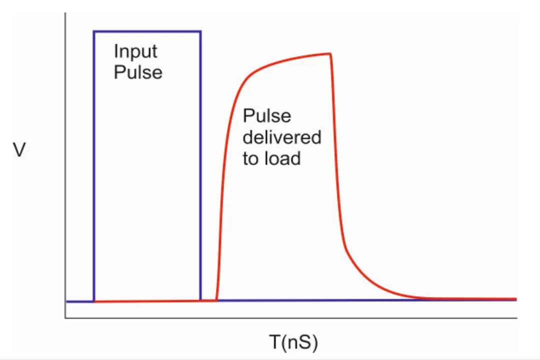
To effectively combat signal degradation, engineers must first be able to measure it accurately. In electrical testing, an oscilloscope, especially one paired with a high-impedance probe, is crucial for observing the time-domain response and measuring signal degradation like overshoot, ringing, and amplitude loss. For analyzing transmission line behavior, Time-Domain Reflectometry () is a standard technique used to locate impedance mismatches or faults along a cable or trace by analyzing reflections.
Controlling attenuation requires addressing the root cause based on the domain:
| Domain | Primary Loss Mechanism | Mitigation Strategy |
|---|---|---|
| Electrical (PCB) | Conductor Resistance/Skin Effect | Use thicker copper plating; optimize trace width for target impedance |
| Electrical (PCB) | Dielectric Loss | Select low dissipation factor () substrate materials (e.g., ) |
| Electrical (General) | Impedance Mismatch | Ensure source, line, and load impedances are matched (e.g., ) |
| Optical Fiber | Absorption | Source high-purity silica and use longer wavelengths () |
| Optical Fiber | Bending | Adhere strictly to specified minimum bend radii during installation |
In many high-performance digital systems, the total attenuation budget must account for the combined effect of all these factors. For instance, a designer might calculate that $20%$ of the budgeted loss is due to the material at the operating frequency, $30%$ is lost due to connector/via insertion loss (a form of mismatch), and the remaining $50%$ is due to the copper trace length. Correcting only the trace length while ignoring the connector loss would still result in an overall system failure to meet the required signal-to-noise ratio at the receiver. Therefore, a thorough attenuation analysis requires evaluating the entire signal path, not just the longest continuous stretch of the conductor or fiber.
Related Questions
#Citations
What is Attenuation? Causes, Effects, and How Signals Weaken
Understanding Signal Attenuation: Causes, Measurement Methods ...
What causes signal attenuation in a PCB and how can it be ...
Understanding Attenuation in Signal Transmission - Technical Articles
Understanding Signal Attenuation in Fiber Optics and How to ...
Attenuation - Wikipedia
Attenuation - GeeksforGeeks
Signal Attenuation in Fiber Optics: Causes, Measurement ... - LINK-PP
What is Attenuation? Meaning & Definition - Keysight Oscilloscope ...