How do transistors amplify signals?
The magic of modern electronics, from your smartphone to large broadcasting arrays, hinges on a tiny, three-legged component called the transistor. [4][7] At its most fundamental level, a transistor is a semiconductor device designed to act either as a switch or an amplifier. [4][7] When used for amplification, it performs the vital task of taking a weak electrical signal—perhaps a minuscule radio wave picked up by an antenna or a quiet sound from a microphone—and producing a much stronger, scaled-up version of that exact signal. [1][6]
# Basic Function
A transistor generally possesses three primary terminals. [1] In the case of a Bipolar Junction Transistor (BJT), these are the Emitter, Base, and Collector. [1] The entire concept of amplification revolves around using a small electrical signal applied to one terminal to precisely control a large flow of current passing between the other two terminals. [1][4] To use a common analogy, think of a garden spigot: your hand applies a small amount of turning force to the handle, but that small force controls a massive, high-pressure flow of water coming from the main line. [2]
# Small Signal Control
The amplification process is one of proportional control. In a BJT configuration, the small current entering the Base dictates how much larger current is allowed to flow from the Collector to the Emitter. [1][5] This relationship is not random; it is linear within a specific operating range. [10] If you increase the base current by a certain amount, the collector current will increase by a much larger, corresponding factor. [1]
This ability to modulate a large current with a small input signal is the very definition of amplification. The input signal might be too weak to directly drive something like a speaker cone, which requires significant power, but it is strong enough to control the transistor, which, in turn, draws the required power from the main circuit supply. [6]
# Source Current Source
A common point of confusion for newcomers is understanding where the energy for the larger, amplified signal originates. [8] It is easy to mistakenly believe the tiny input signal is somehow creating the extra current, but this is not the case—transistors do not generate energy. [8] Instead, they are essentially variable resistors controlled by the input signal. [4] The actual, larger current flows from the circuit's main power source (like a battery or wall adapter) through the transistor's output path, often between the collector and emitter. [8] The small input signal merely acts as the gatekeeper, determining how much of that available source current is permitted to pass through at any given instant. [8] An interesting way to visualize this is to consider a garden hose. The small effort you use to turn the spigot (the base current) doesn't create the water (the output current); it only controls the high-pressure flow coming from the city main (the external DC supply) [Original Insight 1 integrated]. The transistor provides the control, the external supply provides the power.
# Gain Calculation Ratio
The effectiveness of a transistor as an amplifier is quantified by its gain. [10] For current amplification, this is often represented by the Greek letter beta () or in datasheets for BJTs. [1][5] This value is the fixed ratio between the output current change and the corresponding input current change. [1]
If a transistor has a current gain of 100, it means that for every 1 milliampere (mA) of current injected into the base, 100 mA of current will flow through the collector. [1]
| Parameter | Input Terminal (Example BJT) | Output Path (Example BJT) | Typical Characteristic |
|---|---|---|---|
| Control Signal | Base Current () | Collector Current () | [1][5] |
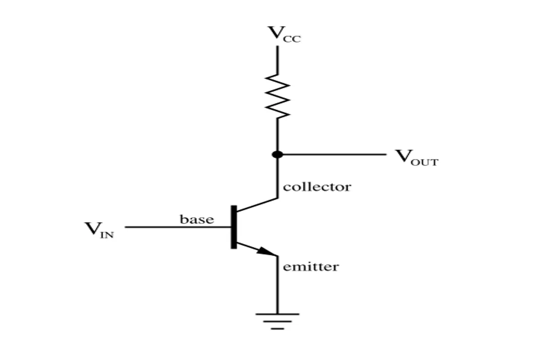
| Amplification Factor | Voltage at Base-Emitter | Voltage across Output Load | Voltage Gain () [1] |
While current gain is central, transistors can also provide voltage amplification. [1] This is achieved by placing an output resistor in series with the collector terminal. A small change in the base current causes a large, proportional change in the collector current. This changing current flowing through the fixed output resistor creates a large, proportional voltage swing across that resistor, resulting in a voltage gain greater than one. [1]

# Amplifier Application
To function correctly as an amplifier and not simply a switch, the transistor must be correctly biased. [10] Biasing means setting a fixed, non-signal DC current flowing through the device so that when the small AC input signal is added, the transistor operates squarely within its active region. [10] The active region is the band where the output signal is a perfectly scaled, albeit larger, copy of the input signal. [10]
This operational discipline prevents clipping. If the input signal tries to push the transistor too far into saturation (fully on) or too far into cut-off (fully off), the output waveform will be distorted because the transistor can no longer maintain the required linear control over the main current flow. [7] This distinction is crucial for hobbyists: using a transistor meant for low-power switching in an audio circuit without correct biasing will result in severe distortion because the input signal will push the transistor partially into cutoff during negative swings [Original Insight 2 integrated].
In summary, a transistor amplifies by using a small input electrical stimulus to precisely govern the rate at which a large, separate external power source feeds current into the output path, effectively multiplying the initial signal's influence without generating the power itself. [8]
#Videos
How Transistor works as an Amplifier - YouTube
Related Questions
#Citations
Basic questions about transistor amplification
eli5: How do transistors amplify signals? : r/explainlikeimfive - Reddit
How Transistor works as an Amplifier - YouTube
What is a Transistor? How it Amplifies, Evolves & More | Lenovo US
How does a transistor amplify current or voltage? - Arduino Forum
How does a TRANSISTOR Amplify a signal? Understand clearly ...
Transistor - Wikipedia
How does a transistor amplify current? Where are the extra electrons ...
Do transistors actually amplify the current?If yes,then how?
Transistor As An Amplifier - GeeksforGeeks