What causes energy loss during transmission?

The journey electricity takes from a distant power plant to your home outlet is a marvel of modern engineering, yet it is not entirely lossless. Every time power is moved across the high-voltage network, a fraction of that energy dissipates before it can do any work. These unavoidable energy reductions, often referred to as line losses, are inherent to moving electricity through physical conductors, and understanding their source is the first step in minimizing them and keeping energy costs down. [3]
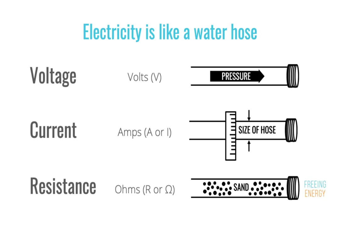
The core issue is that conductors—the metal lines and wires—are not perfect pathways. When current attempts to flow, it meets opposition, and this opposition manifests primarily as heat that warms the wire and the surrounding air. [3][5][7]
# Resistive Heat
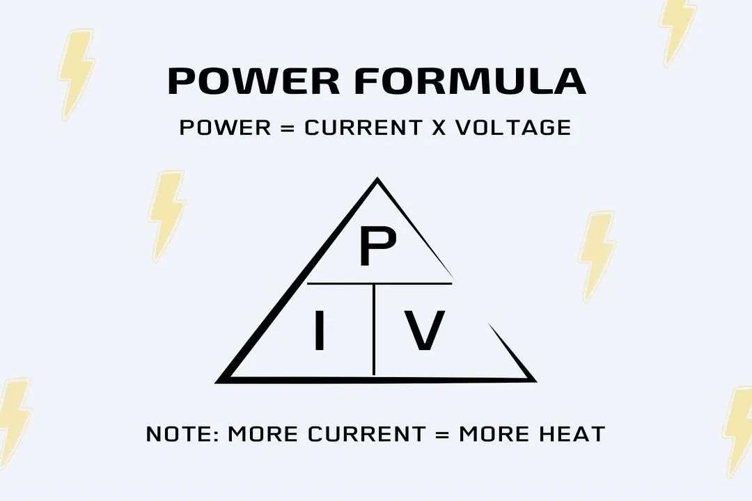
The dominant cause of energy wastage in transmission and distribution systems stems directly from the electrical resistance of the conductors. [3][5] This is commonly understood through Joule's Law, which mathematically states that the power lost () is proportional to the resistance () multiplied by the square of the current (). [3][7]
This quadratic relationship is crucial: if the current flowing through a line doubles, the heat lost due to resistance quadruples, even if the resistance stays the same. [1][7] Therefore, any factor that increases the current flow—such as delivering more power or having a poor power factor—results in a disproportionately large increase in wasted energy. [6][8]
The resistance () itself is determined by the material and the physical dimensions of the line. Longer transmission routes naturally accumulate more resistance simply because there is more length () of conductor material involved. [3][8] Furthermore, the material's resistivity () plays a role; copper and aluminum are standard, but any material will exhibit some inherent resistance. [7] Even within the conductor, at the standard alternating current () frequency of or , the skin effect can be significant. This phenomenon forces the current to concentrate near the surface of the conductor, effectively reducing the usable cross-sectional area and thereby increasing the effective resistance experienced by the current flow. [4][7]
# Voltage Strategy
Since the primary driver of resistive loss is the current squared (), the most effective way to minimize this loss over long distances is by minimizing the current itself. [2][4] Power () delivered is the product of voltage () and current (), i.e., . [4]
To transmit a fixed amount of power, one can choose high current/low voltage or low current/high voltage. [1][7] The electrical grid overwhelmingly chooses the latter for bulk transport. By stepping the voltage up—often into the hundreds of thousands of volts—the required current drops dramatically, and consequently, the heat loss is drastically reduced. [2][4] This high-voltage approach is why power won the "War of the Currents" in the late century, thanks to the relative ease of using transformers to step voltages up and down without major efficiency hits. [4]
However, this mathematical efficiency comes with a physical price tag. While lowering current minimizes operational loss, transmitting power at extremely high voltages means the electrical potential difference between the conductor and the ground, or between adjacent conductors, is vast. [7] This requires much taller support towers, significantly wider spacing between wires, and thicker, more expensive insulation to prevent dangerous arcing or flashovers. [4][7] The choice of transmission voltage is thus an engineering trade-off: finding the level that minimizes the long-term cost of lost energy while balancing the massive initial capital investment in robust infrastructure. [7]
# Other Dissipations
While resistive losses account for the bulk of energy dissipated as heat in the wires themselves, transmission introduces other forms of energy wastage related to the system’s reactive properties. [3][4] Direct current () systems, which have a steady voltage, avoid these issues entirely, which is why High-Voltage Direct Current () links are considered superior for very long-distance point-to-point connections. [4]
# Reactive Losses
For systems, energy is lost through two main reactive mechanisms tied to the oscillating nature of the current:
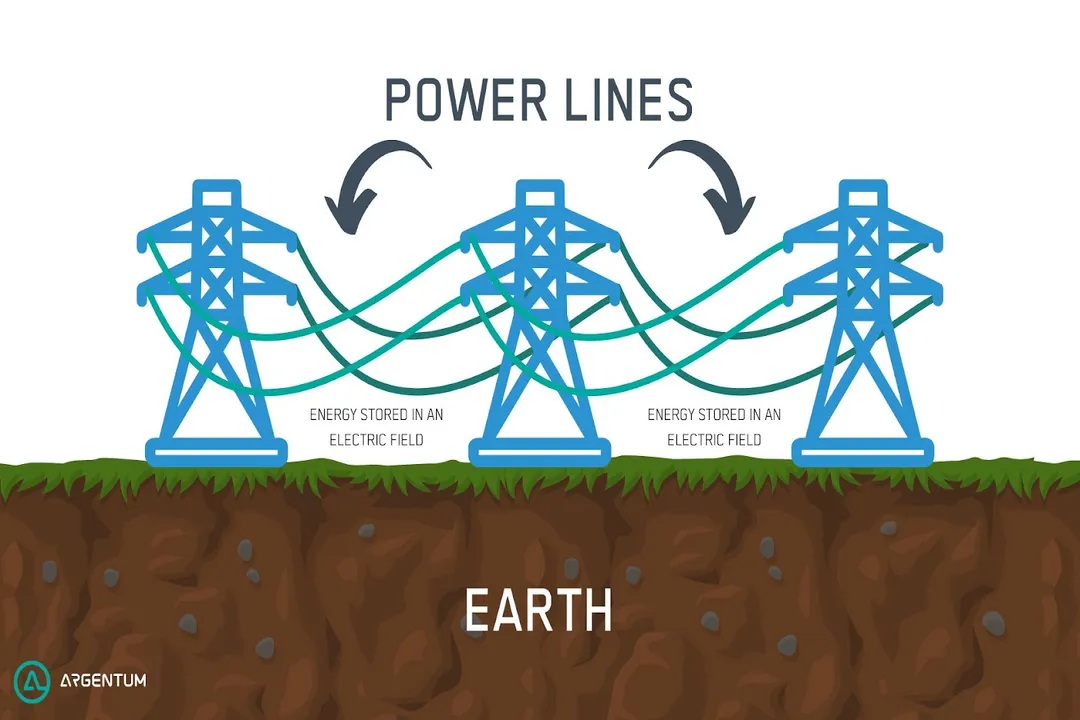
- Capacitive Losses: Every power line acts as one plate of a capacitor, with the earth acting as the other. [4] As the voltage alternates, an electric field builds up and collapses between the line and the ground. Energy is stored and released during this cycle, leading to dissipated heat known as capacitive loss. [3][4] Keeping lines higher off the ground lessens the electric field interaction with the earth, reducing this effect. [4]
- Inductive Losses: Similarly, the changing magnetic field created by the alternating current causes the line to act as an inductor. [4] Energy stored within this fluctuating magnetic field is not delivered to the load and is dissipated as heat during each cycle. [3][4]
# Transformer Inefficiencies
Energy also dissipates within the equipment necessary to change the voltage levels. Transformers, essential for stepping voltage up at the source and down at substations, contribute to two categories of loss: [5][7]
- Fixed Losses (No-Load): These occur just by having the transformer energized, independent of the actual load. They include hysteresis losses (energy lost as the magnetic polarity of the core reverses with every cycle) and eddy current losses (unwanted circulating currents induced in the transformer’s iron core). [6]
- Variable Losses (Copper Losses): These are the resistive () losses within the transformer windings, which increase with the current flowing through them. [6]
If you compare a high-voltage transmission system to a low-voltage system, the high-voltage is typically more efficient. However, if you compare and at the same high voltage, the system will always be less efficient because it incurs the resistive loss plus the capacitive and inductive losses. [4]
# Loss Totals
The percentage of energy lost varies significantly depending on the quality of the infrastructure and the distance traveled. [2][5] In the 's transmission network, estimates suggest approximately $1.7%$ of power is lost transporting bulk energy at high voltage. [5] When you add the lower-voltage distribution network—the lines from the substation to the final customer—the combined loss figure can rise. For instance, in the , total transmission and distribution losses are often cited in the $5%$ to $6%$ range, with distribution losses () being relatively higher than transmission losses () because distribution operates at lower voltages and higher currents. [2][5] Countries with less developed infrastructure or higher rates of energy diversion can see total system losses exceeding $30%$. [2]

# System Effects
Beyond the fundamental resistive and reactive components, real-world grid operation introduces other subtle inefficiencies that contribute to overall loss:
- Power Factor: When the power factor is less than one (unity), the system must carry a higher current to deliver the same amount of real (usable) power, increasing losses. [6] Industrial users with large motors or electronics often contribute to this by creating a lagging power factor. [6]
- Phase Imbalance: Electricity grids typically run on three phases. If the load is not distributed perfectly evenly across these three phases, the current in the overloaded phases must increase to meet demand. Due to the quadratic nature of loss, this imbalance leads to higher overall system losses than if the load were perfectly balanced. [6] For industrial customers, actively managing load balancing across phases can provide immediate, measurable savings by reducing localized current peaks. [6]
- Harmonics: Distortions in the pure waveform, often created by modern electronics, can lead to additional heating losses () that are not accounted for in simple power factor calculations. [6]
# Unofficial Losses
It is also important to separate technical losses from non-technical losses, which are tied to administrative errors or illegal activity. [6] Non-technical losses include energy that is consumed but never accurately accounted for. This typically involves electricity theft—illegal connections that bypass meters entirely—or inaccuracies in estimating usage for supplies that are legitimately unmetered, such as street lighting. [6] While improving line efficiency targets technical issues like conductor resistance, reducing these non-technical losses through better auditing and security is necessary to ensure that the energy paid for is the energy delivered. [2][6]
In summary, energy loss during transmission is an interplay between the wire's intrinsic resistance and the physics of alternating current. While the high-voltage strategy successfully combats the dominant resistive heat loss, operators must constantly manage secondary effects like reactive power components, localized load imbalances, and transformer efficiencies to ensure the power that leaves the plant is as close as possible to the power that arrives at the meter. [3][6]
Related Questions
#Citations
Understanding Line Losses In Energy Transmission | Diversegy
Lost In Transmission: How Much Electricity Disappears Between A ...
3 Types of Line Losses in Power Transmission
ELI5: Why does high voltage reduce electrical transmission loss?
What causes power losses in transmission lines?
What causes Losses? - National Grid
[PDF] Transmission Losses - National Energy System Operator
How Much Power Loss in Transmission Lines - CHINT Global