What is the principle behind fiber optics?
The transmission of light signals across vast distances or within a compact device, enabling the high-speed data flow we rely on daily, is governed by a surprisingly elegant physical phenomenon. This technique, known as fiber optics, moves information as pulses of light traveling through incredibly thin strands of glass or plastic, essentially trapping that light and guiding it around corners and over kilometers without significant signal decay. The fundamental success of this method hinges on manipulating how light behaves when it crosses the boundary between two different materials, a concept rooted deeply in the physics of light itself.
# Light Bending
To grasp the mechanism, one must first understand refraction, which is the change in direction that occurs when a light wave passes from one transparent medium into another. This bending happens because light travels at different speeds through different substances. For instance, light moves slower in water than it does in air, causing it to change its path as it enters the water surface at an angle. The relationship between the angle of incidence (the angle at which the light hits the boundary) and the angle of refraction (the angle at which it passes into the new material) is precisely described by Snell's Law.
The degree to which a material slows down or bends light is quantified by its refractive index. A higher refractive index means light travels slower through that medium, and the light bends more toward the normal (an imaginary line perpendicular to the surface) when entering that material from a less dense medium. In the context of fiber optics, this difference in speed and angle is not just incidental; it is the critical lever used to keep the light confined within the transmission pathway.
# Fiber Anatomy
A typical optical fiber, often thinner than a human hair, is specifically engineered with multiple concentric layers, each material chosen for its precise optical properties. The structure is usually composed of three main parts: the core, the cladding, and the protective buffer coating.
The core is the very center of the fiber, the pathway through which the light actually travels. This inner strand must be made of a material that allows light to pass through it with minimal absorption or scattering. Crucially, the core is manufactured with a higher refractive index than the surrounding layer.
Surrounding the core is the cladding. The cladding’s primary function is optical: it must have a lower refractive index than the core. This contrast between the core and the cladding refractive indices is the entire mechanical basis for trapping the light signal. While the core carries the data-bearing light, the cladding acts as the optical mirror, forcing the light to stay inside the core region.
Outside the cladding is the protective buffer coating. This layer is not involved in the light transmission principle itself; rather, it serves a mechanical role, protecting the delicate glass structure from moisture, physical damage, and abrasion during handling and installation. If the core or cladding is scratched or cracked, the light signal will escape, leading to signal loss, which is why careful handling during fusion splicing is paramount in field installations. Maintaining the integrity of the glass-to-glass interface between the core and cladding is arguably the single greatest engineering challenge in creating a high-quality, long-haul fiber cable.

# Reflection Principle
The core principle that makes fiber optics functional is Total Internal Reflection (TIR). This phenomenon occurs only under very specific conditions involving the interaction of light with the boundary between two media that have different refractive indices, as described above.
When light travels from a denser medium (the core, higher index) to a less dense medium (the cladding, lower index), it bends away from the normal line. If the light ray strikes the boundary at a shallow angle, it will refract out into the cladding and be lost—this is standard reflection and refraction. However, if the angle at which the light hits the boundary is shallow enough—meaning the angle of incidence is greater than a specific critical angle—the light is not refracted out at all. Instead, all of the light is perfectly reflected back into the denser medium, the core. This is total internal reflection.
Imagine the inside of the fiber as a perfectly reflective pipe. As the light pulse enters the fiber at the correct angle, it travels down the core, hitting the boundary with the cladding millions of times per second, and with every single collision, it is reflected perfectly back into the core path, never escaping into the cladding. This continuous, 100% efficient reflection allows the signal to propagate over great distances with extremely low attenuation, far superior to the energy loss seen when transmitting electrical signals over traditional copper wires.
# Angle Dependence
The requirement for total internal reflection introduces a specific constraint on how the light signal must enter the fiber. This constraint is defined by the critical angle, which is unique to the pair of materials used for the core and cladding.
If the input light ray strikes the end-face of the fiber perfectly straight on (at a 90-degree angle to the surface, or 0 degrees incidence relative to the fiber axis), it will pass straight down the core without reflecting. If the light enters too steeply, meaning the angle of incidence at the boundary is less than this critical angle, some light will leak out into the cladding, leading to signal degradation, a process known as fray or loss.
Therefore, the acceptance cone for light entering the fiber is limited by this critical angle. This is why specialized connection equipment is necessary; you cannot simply shine a flashlight into an optical cable and expect perfect transmission over a long distance unless the light source is coupled correctly to ensure that the rays entering the core strike the core-cladding interface at angles greater than the critical angle. This concept ties directly into the Numerical Aperture (NA) of the fiber, which mathematically describes the range of angles over which the fiber can accept and transmit light. A higher NA means the fiber can accept light over a wider range of angles, making coupling easier, although it may also introduce more intermodal dispersion in certain fiber types.
For context, consider a standard multi-mode fiber designed for short-range data. If the core material has a refractive index of approximately and the cladding is , the critical angle will be very small, requiring light to strike the boundary at a relatively shallow angle to achieve TIR. If you were to install such a cable and then later need to splice it, any misalignment or gap exceeding a few microns where two fibers meet will cause a sudden, massive drop in signal strength because the perfectly polished core interface is no longer maintained, and TIR ceases across the gap. This extreme sensitivity to the interface quality is one reason why fiber installation requires a higher level of specialized skill compared to simply terminating a copper coaxial cable.

# Transmission Medium
While the principle of TIR keeps the light within the core, the quality of the transmission over distance is also dependent on the purity of the material itself. Optical fibers are made primarily of highly purified silica glass, though plastic optical fibers (POF) exist for shorter, less demanding applications.
Silica is chosen because it is highly transparent to the infrared light wavelengths typically used for long-distance telecommunications, often around or . At these wavelengths, the glass allows the light signal to travel tens or even hundreds of kilometers before the signal strength drops to a level requiring amplification or regeneration. Signal loss, or attenuation, in fiber optic cables is measured in decibels per kilometer () and is significantly lower than the attenuation experienced by electrical signals in copper conductors.
The light pulse itself is generated by a semiconductor laser or a Light Emitting Diode (LED) at one end of the cable. This light source converts electrical data (ones and zeros) into rapid pulses of light. These light pulses follow the path dictated by Total Internal Reflection all the way to the receiving end, where a photodetector converts the light back into an electrical signal readable by a computer or network device.
# Fiber Types
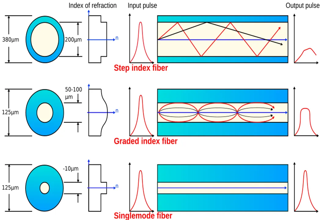
The principle of TIR remains the same across different fiber designs, but the way the light travels within the core changes based on the fiber's construction, leading to different performance characteristics. There are two primary categories: single-mode and multi-mode fiber.
# Single Mode
Single-mode fiber (SMF) has an extremely narrow core, often just $9$ micrometers in diameter. This small size forces the light to travel along essentially one single path, or mode, down the center of the fiber. Because there is only one path, the light pulses arrive at the destination nearly simultaneously, minimizing signal spreading over time, which is known as dispersion. This lack of significant modal dispersion is what allows SMF to carry data at extremely high rates over very long distances, making it the standard for undersea cables and backbone networks.
# Multi Mode
Multi-mode fiber (MMF) has a much wider core, typically $50$ or $62.5$ micrometers. Because the core is larger, light can enter at many different angles, resulting in many different paths, or modes, through which the light travels simultaneously. A ray of light that travels straight down the center of the core will reach the end sooner than a ray that zigzags near the edge of the cladding. This difference in travel time for different light paths causes modal dispersion, which spreads the light pulse out as it travels. This dispersion limits the distance and maximum bandwidth achievable with MMF compared to SMF, but MMF remains cost-effective and perfectly suitable for shorter links, such as those within a building or a local data center.
# Materials and Engineering
While the physics of TIR is straightforward—light hits a boundary at an angle greater than the critical angle and is reflected—the engineering required to make this happen reliably for decades is anything but simple. High-performance fibers rely on the purity of the silica glass. Impurities in the glass structure or imperfections in the glass-cladding interface can cause scattering, where light is bounced off in random directions rather than reflecting cleanly back into the core, leading to signal loss.
For example, the difference in refractive index between the core and cladding can be achieved in two primary ways. One method is doping the core material with an element like germanium to increase its index relative to the pure silica cladding. Another way involves designing a graded-index fiber, where the refractive index of the core is highest at the very center and gradually decreases smoothly toward the cladding. In this graded design, light rays traveling in the outer paths (closer to the cladding) actually travel slightly faster than the rays near the center, which helps to equalize the arrival times and combat modal dispersion in multi-mode applications.
The practical application of this principle also demands precision at the connection points. When joining two fiber ends, whether by fusion splicing (melting them together) or using mechanical connectors, the two cores must align almost perfectly, often within one or two microns, for the TIR path to continue uninterrupted across the joint. If you are troubleshooting a network, remembering that the light is traveling by reflecting off a boundary requires you to think about loss differently than with copper; in copper, you worry about resistance along the wire's length; in fiber, you must worry about the smoothness and alignment of the walls of the transmission channel. Any significant dirt particle, scratch, or misalignment on the end-face of a connector can completely disrupt the total internal reflection, causing most of the signal energy to leak out immediately at that point, an issue that an optical power meter can detect instantly. This reliance on perfect internal reflection is the principle that gives fiber optics its incredible speed and low loss characteristics.
#Videos
How Fiber Optics Works - YouTube
Related Questions
#Citations
Optical fiber - Wikipedia
Basic Principles of Fiber Optics Series: Refraction - trueCABLE
What Is Optical Fiber Technology, and How Does It Work? - NAI Group
What are Fiber Optics and How Do They Work? - Coherent
The Science Behind Fiber Optic Cabling
How do fiber optic cables work? : r/askscience - Reddit
Understanding the Fundamentals of Optical Fiber Technology
What is the principle of the operation of fibre optics? - Quora
How Fiber Optics Works - YouTube